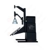
LM-79 Goniophotomètre à détecteur mobile (miroir de type C)
LSG-6000
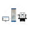
Goniophotomètre de luminaire à rotation de haute précision
LSG-1890B
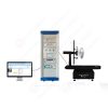
Goniospectroradiomètre de luminaire à rotation de haute précision
LSG-1890BCCD

Goniophotomètre pour automobile et lampes de signalisation
LSG-1950
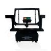
Goniophotomètre pour feux de signalisation routière (modèle économique)
LSG-1950S
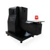
Dispositif d'alerte visuelle d'alarme incendie VAD Goniophotomètre
LSG-1930
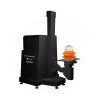
Goniophotomètre pour l'éclairage des pistes d'aérodrome
LSG-1940
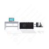
Goniophotomètre compact
LSG-1200A
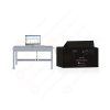
Goniophotomètre à LED
LSG-1100
Goniophotomètre à détecteur de champ proche
LSG-1900B
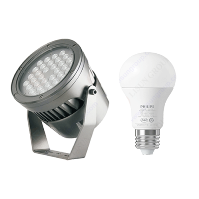 Solutions de test pour LED et luminaires
 LM-79 et LM-80 Solutions de test
 Solutions de test de pilotes LED
 Solutions de test pour appareils ménagers
 Solutions de test mobile et réseau
 Solutions de test pour l'électronique automobile
 Solutions de tests audio-vidéo et informatiques
 Solutions de test de câbles et fils
 Solutions de test pour fiches et prises
 Solutions de test d'interrupteur d'alimentation
 Solutions de test de transformateur
 Solutions de test pour jouets électriques
 Solutions de test de compteurs d'énergie
 Solutions de test d'outils motorisés
Sélectionnez une organisation
consulter les normes
Abstract
With the widespread adoption of LED lighting products, high-frequency electromagnetic disturbances generated by switching power supplies have become increasingly prominent. As the dominant international standard for radio disturbance characteristics of lighting equipment, CISPR 15:2018 has updated the test requirements for the 30‑300 MHz frequency band. Traditional radiated emission testing on an open test site suffers from high site construction costs, heavy ambient interference and long test cycles. A Coupling and Decoupling Network provides an alternative test method for high-frequency electromagnetic disturbance measurement of lighting devices. When an EMI receiver is used together with the CDNE-M316 or CDNE-M216 Coupling and Decoupling Network, it is equivalent to conducting electromagnetic radiated disturbance tests in the frequency range of 30 to 300 MHz, and the test results fully comply with the provisions of CISPR 15:2018. This paper focuses on the LISUN CDNE-M316 Coupling and Decoupling Network. It elaborates on the working principle, key technical parameters and setup guidelines of the test system, compares the differences between conventional radiated emission tests and the Coupling and Decoupling Network method, and analyzes its practical application in lighting EMC testing. It offers references for luminaire R&D, certification testing and laboratory instrument selection.
CISPR 15:2018 corresponds to the domestic standard GB 17743, which specifies disturbance limits and measurement methods for electrical lighting and similar equipment. For the 30‑300 MHz band, the conventional method relies on antennas placed in an open-area test site or semi-anechoic chamber to capture radiated interference signals. This type of test imposes strict constraints on site environment, grounding conditions and background noise, making it difficult for small and medium-sized enterprises to build a complete radiated test laboratory. Annex J of CISPR 15:2018 introduces the alternative test method using a Coupling and Decoupling Network. This method evaluates the high-frequency radiated emission level of the lighting equipment under test indirectly by measuring common-mode disturbance voltage on the power port. Under applicable conditions, this method has equivalent validity to radiated emission testing and can be applied to pre-compliance testing and certain certification tests.
A Réseau de couplage et de découplage consists of two core functional units: the coupling section and the decoupling section. The coupling unit extracts high-frequency common-mode disturbance signals from the power line of the equipment under test (EUT) and transmits interference signals to the measurement port of the EMI receiver. The decoupling unit creates high-impedance isolation for the auxiliary equipment (AE) side, preventing noise from the auxiliary power supply from flowing back into the measurement loop and distorting the measured data. The LISUN CDNE-M316 Coupling and Decoupling Network is designed for single-phase lighting equipment with L+N+PE three-wire circuits, while CDNE-M216 is suitable for two-wire samples without a protective earth conductor. When an EMI receiver is used together with the CDNE-M316 or CDNE-M216 Coupling and Decoupling Network, the setup is equivalent to performing electromagnetic radiated disturbance tests from 30 MHz to 300 MHz. This test solution eliminates the need for a large anechoic chamber and receiving antenna. A test bench can be built simply with an EMI receiver and a Coupling and Decoupling Network, significantly lowering the threshold for pre-testing high-frequency disturbances of lighting products.
In terms of hardware design, low-parasitic inductance coupling capacitors inside the Coupling and Decoupling Network isolate mains power from radio-frequency signals. 50 Hz utility power can be supplied normally to the lighting luminaire under test, while high-frequency disturbance signals from 30 MHz to 300 MHz are coupled out to the BNC measurement port. Decoupling chokes present high impedance to radio-frequency interference and provide isolation above 30 dB between the EUT port and the AE port, suppressing external interference introduced by the power supply loop. Meanwhile, the Coupling and Decoupling Network maintains the common-mode impedance at 150 Ω ±20% across the 30‑300 MHz band. This impedance specification directly determines the accuracy of disturbance voltage acquisition and is a key technical requirement specified in CISPR 15:2018.
| Élément de paramètre | Spécifications | Norme applicable |
|---|---|---|
| Plage de fréquence de fonctionnement | 30 MHz‑300 MHz (230‑300 MHz as optional configuration) | CISPR 15:2018 |
| Maximum Current at EUT Port | 16 A (CA/CC) | CEI 60947-1 |
| Tension | Line-to-line 250 V AC; Line-to-earth 500 V AC | EN 55015 |
| Decoupling Efficiency from EUT to AE | ≥30 dB | CISPR 15:2018 Annex J |
| Coupling Attenuation at BNC Measurement Port | 20 dB | CISPR 15:2018 Figure J.2 |
| Common-mode Impedance, 30‑300 MHz | 150 ±20% | CEI 61000‑4‑6 |
| Connectors for EUT and AE Ports | Douilles bananes de sécurité de 4 mm | EN 61010-1 |
| Applicable EUT Circuit | L+N+PE single-phase three-wire | CISPR 15:2018 Annex J |
A complete test system consists of an EMI receiver, a Coupling and Decoupling Network, an auxiliary power supply and a reference ground plane. The lighting luminaire under test is connected to the EUT port of the Coupling and Decoupling Network, the auxiliary power supply is connected to the AE port, and the BNC measurement port is linked to the EMI receiver through a 50 Ω RF cable. The Coupling and Decoupling Network shall be placed on a standard reference ground plane with reliable earthing of the enclosure. Improper grounding will alter the common-mode impedance directly and introduce systematic measurement deviations. If the product under test has no protective earth conductor, the CDNE-M216 Coupling and Decoupling Network shall be selected; the rest of the system setup follows the same logic as CDNE-M316.
Before testing, confirm that the Coupling and Decoupling Network is within its valid calibration cycle. Configure the EMI receiver according to CISPR 15:2018, including intermediate frequency bandwidth, detector mode and sweep time. Power on the luminaire and allow it to operate stably. The receiver sweeps across the full 30‑300 MHz band, reads disturbance voltage values at each frequency point, and compares readings against standard limit lines to judge compliance. Operators need to understand the boundary of this alternative method. CISPR 15:2018 specifies that the equivalent radiated test using a Coupling and Decoupling Network is mainly applicable to lighting equipment with an internal clock frequency not higher than 30 MHz. Samples beyond this scope still require conventional radiated emission testing in an anechoic chamber.
During measurement, avoid sharp bends in RF cables and keep cables away from strong interference sources. Check BNC connections regularly; poor contact introduces extra attenuation and reflection and leads to underestimated measurement results. After data acquisition, disturbance voltage data captured by the EMI receiver, combined with the coupling attenuation factor of the Coupling and Decoupling Network, are converted into equivalent radiated disturbance levels for CISPR 15:2018 radiated emission compliance assessment.
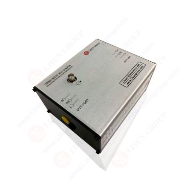
CDNE-M316_Coupling Decoupling Network for Communication Lines
For LED luminaire manufacturers, the Coupling and Decoupling Network supports fast pre-compliance testing in the R&D stage. Without booking an anechoic chamber, engineers can troubleshoot high-frequency disturbances from 30 MHz to 300 MHz inside their own laboratory. Switching power supply and drive circuit interference issues can be identified at the prototype stage, enabling adjustment of filter circuits and PCB layout and reducing rework costs caused by certification failure. For production quality control, some manufacturers use a Coupling and Decoupling Network for sampling screening of finished products to monitor EMC consistency across batches.
Third-party test laboratories can adopt the Coupling and Decoupling Network as an auxiliary tool for pre-screening, filtering out obviously non-compliant samples in advance and saving chamber time. It should be clarified that results obtained from a Coupling and Decoupling Network are equivalent measurements. Not all certification bodies accept this method as formal type-test evidence, and official certification tests shall follow the detailed rules defined by the respective certification authority. The LISUN CDNE-M316 Coupling and Decoupling Network can be matched with the EMI-9KB EMI test system to form a complete lighting EMI test platform, covering conducted disturbance from 9 kHz to 30 MHz and equivalent radiated testing from 30 MHz to 300 MHz by the Coupling and Decoupling Network method.
The CDNE-M216 and CDNE-M316 Coupling and Decoupling Networks cover lighting products with two-wire and three-wire power supply structures respectively. From small LED bulbs and panel lights to high-power outdoor floodlights, this solution can be used for preliminary evaluation as long as the sample falls within the applicable scope of the standard. It serves as a powerful test instrument for lighting products targeting GB 17743 in the domestic market and EN 55015 / CISPR 15:2018 for export to the European Union.
CISPR 15:2018 imposes stricter control over high-frequency electromagnetic disturbances from modern lighting devices. Conventional radiated emission testing is heavily restricted by site conditions, while the Coupling and Decoupling Network provides an efficient and feasible alternative measurement path. When an EMI receiver is used together with the CDNE-M316 or CDNE-M216 Réseau de couplage et de découplage, the configuration is equivalent to conducting electromagnetic radiated disturbance tests at 30 to 300 MHz and fully meets the technical specifications of CISPR 15:2018. The LISUN CDNE-M316 Coupling and Decoupling Network delivers reliable equivalent radiated test data through well-controlled common-mode impedance and high-performance decoupling. In practical use, operators must strictly follow standard setup requirements, recognize the applicable scope of this method and distinguish between pre-testing and formal certification testing. The Coupling and Decoupling Network addresses the limitation of small and medium lighting enterprises without access to an anechoic chamber. It helps R&D engineers quickly locate high-frequency EMC risks and is practically valuable for improving the overall EMC performance of domestic lighting products.
Mots clés:CDNE-M316Votre adresse électronique ne sera pas publiée. Les champs obligatoires sont marqués *

 Anglais
 中文简体
 Русский
 Español
 Português
 Türkçe
 العربية
 Deutsch
 Polski
 Italiano
 Français
 한국어
 ไทย
 Tiếng Việt
 日本語